Contents :
Preliminaries to Circuit Evaluation
Goal and Overview
1.1 What Are Electrical Circuits and What Are They Used For?
1.2 What Legal guidelines Govern the Conduct of Electrical Circuits?
1.Three What Is Electrical Present?
1.Four What Is the Route of Present?
1.5 What Is Voltage?
1.6 What Is Voltage Polarity?
1.7 How Are Vitality and Energy Associated to Voltage and Present?
1.7.1 Optimistic and Adverse Values of Circuit Variables
1.Eight What Are Very best Circuit Parts and How Do They Deal with Vitality?
1.9 Why Resistance, Capacitance, and Inductance?
1.10 What Are the Approximations Implicit in Fundamental Electrical Circuits?
Studying Guidelines: What Ought to Be Discovered from This Chapter
Drawback-Fixing Suggestions
Issues
Fundamentals of Resistive Circuits
Goal and Overview
2.1 Nature of Resistance
2.2 Very best Resistor
2.Three Brief Circuit and Open Circuit
2.Four Very best, Unbiased Voltage Supply
2.5 Very best, Unbiased Present Supply
2.6 Very best, Dependent Sources
2.6.1 Very best, Dependent Voltage Sources
2.6.2 Very best, Dependent Present Sources
2.7 Nomenclature and Evaluation of Resistive Circuits
2.Eight Kirchhoff’s Legal guidelines
2.8.1 Kirchhoff’s Present Legislation
2.8.2 Kirchhoff’s Voltage Legislation
2.9 Collection and Parallel Connections
2.9.1 Collection Connection
2.9.2 Parallel Connection
2.10 Drawback-Fixing Strategy
Studying Guidelines: What Ought to Be Discovered from This Chapter
Drawback-Fixing Suggestions
Issues
Responses of Collection RLC Circuit with
Preliminary Vitality Storage (Instance 12.3) 348
Pressured Responses of Parallel GCL Circuit
with Preliminary Vitality Storage (Instance 12.4) 350
Pressured Responses of Collection RLC Circuit
with Dependent Supply and Preliminary
Vitality Storage (Instance 12.5) 351
Enter–Output Attribute of the
Op Amp in PSpice (Instance 13.1) 369
Noninverting Configuration
(Instance 13.2) 374
Unity-Achieve Amplifier (Instance 13.3) 376
Inverting Configuration (Instance 13.5) 380
Noninverting Integrator (Instance 13.7) 384
Instrumentation Amplifier (Instance 13.8) 386
Two-Stage Amplifier (Instance 13.10) 390
Response of uA741 Sensible Op Amp
(Instance 13.11) 391
First-Order Responses (Instance 14.1) 416
Second-Order Bandpass RC Circuit
(Instance 14.2) 420
Bode Plots of Second-Order Low-Cross
Response (Instance 14.3) 424
Bode Plots of Second-Order Excessive-Cross
Response (Instance 14.4) 426
Parallel GCL Circuit (Instance 14.5) 430
Bandstop Response (Instance 14.6) 431
Second-Order and Third-Order
Butterworth Low-Cross Filters
(Instance 15.1) 450
Second-Order and Third-Order
Butterworth Excessive-Cross Filters
(Instance 15.2) 451
Broadband Bandpass Filter (Instance 15.3) 455
Second-Order Noninverting Excessive-Cross
Butterworth Filter (Instance 15.4) 458
Third-Order Noninverting Butterworth
Low-Cross Filter (Instance 15.5) 459
Second-Order Inverting Bandpass Filter
(Instance 15.6) 460
Notch Filter (Instance 15.7) 463
Fourier Evaluation of Sq. Wave
(Instance 16.4) 482
Half-Wave and Full-Wave Rectified
Waveforms (Instance 16.6) 491
Fourier Simulation of Integral of Sq.
Wave (Instance 16.7) 493
Fourier Simulation of Piece-Clever Linear
Waveforms (Instance 16.8)
About this book :
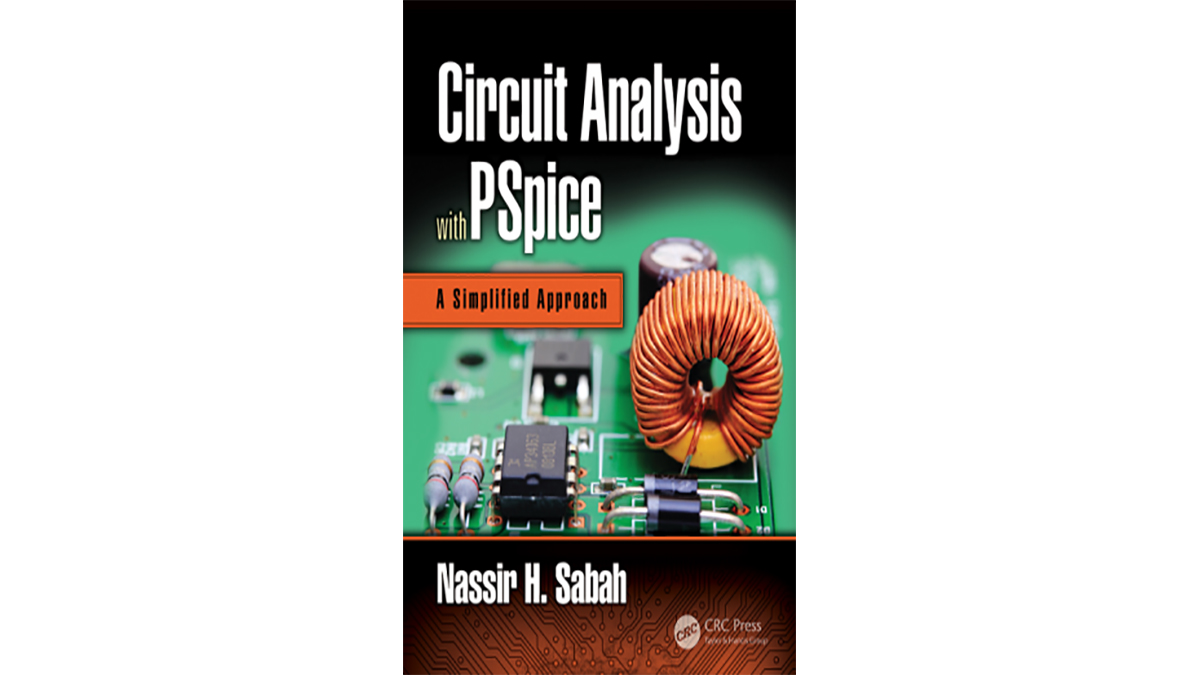
This guide is greater than a textbook on electrical circuits. It’s a veritable studying reference that presents electrical circuit evaluation in a simplified method, with out sacrificing rigor and thoroughness.
The guide is a sequel to the writer’s Electrical Circuits and Indicators, CRC Press, 2008. The electrical sign materials has been omitted and circuit evaluation is handled in a extra simplified and expanded kind. The guide differs from different textbooks on electrical circuits in its pedagogy and group, as expounded later, notably within the following respects:
1. Robust emphasis on (a) easy, clear, cautious, and complete explanations of the essential ideas in circuit evaluation (simplicity is to not be construed as superficiality; what is supposed is straightforward and clear, however in-depth, explanations); (b) a sound understanding of fundamentals, enhanced by bodily and insightful interpretations of circuit conduct.
And (c) intensive use of PSpice® (OrCAD, PSpice, SPECTRA for OrCAD, and Cadence are registered logos of Cadence Design Programs, Inc., San Jose, California), as detailed later in a bit on PSpice simulations.
2. Efficient downside fixing based mostly on (a) a scientific, logical, and imaginative method, having the acronym ISDEPIC, formulated by the writer and refined over the previous a number of years by interplay with college students
And (b) presenting a wide range of subjects and examples that foster problem-solving abilities by encouraging the scholar to view an issue in several methods, notably contemporary and unique methods, based on a sound understanding of fundamentals.
The writer firmly believes {that a} course on electrical circuits offers a superb alternative to nurture problem-solving abilities, as a central goal of high quality engineering schooling. That’s the reason some subjects, similar to exploitation of symmetry in electrical circuits, are included, though they’re of restricted sensible significance.
3. Substantive utility of the substitution theorem and of duality to facilitate circuit evaluation and improve the understanding of circuit conduct.

